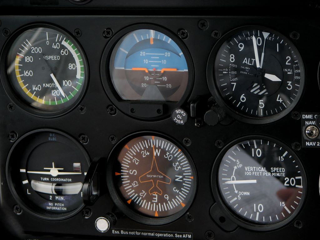
Basic Aircraft Instruments - A quick scan of six packets gives the pilot current information on aircraft speed, altitude, climb/descent, attitude, heading and turn/bank. Individually, the six packs are:
The instruments in the six packages operate through different flight systems. The ASI, altimeter, and VSI use a pitot-static system that provides air pressure from the pitot tube and ambient pressure from the port. Only ASI uses pitot tubes; all three applications use static ports.
Basic Aircraft Instruments

AI, HI and Inversion indicators are gyroscopes with internal gyroscopes powered by air, pressure or electricity.
File:basic Flight Instruments.svg
The ASI uses the pressure differential in the Pitot-static system to measure and display the aircraft's speed. On most aircraft, ASI displays speed in knots or kilometers per hour. The needle points to the current indicated airspeed (IAS). Color-coded flags provide key speed information for that type of aircraft, including stall, flap setting, normal operation, warning and no speeding. The table below shows what the colors on the wind speed indicator mean.
Also known as Space, the AI uses its internal gyroscopes to show exactly how the plane is in the sky. The display consists of a small plane that fits horizontally and horizontally to the sky, with a blue sky above and a brown or black ground below.
A vertical scale in the sky indicates how far the sound is going up or down. The curved number at the top indicates the extent of the left or right bank. As the aircraft changes altitude or direction, the aircraft rotates around the gyroscope AI and the instrument displays respond.
The altimeter uses the air pressure obtained from a static station to indicate the aircraft altitude (MSL) in feet. Three hands provide altitude information in increments of 100, 1,000 and 10,000 feet.
File:six Flight Instruments.jpg
Because air pressure varies with altitude and atmospheric conditions, most altimeters have a variable adjustment that dials in the local air pressure (also known as the barometric altimeter setting).
The TC uses a tilting internal gyroscope to display the initial scroll rate and steady rate of rotation. The silhouette of the aircraft mimics the direction of rotation of the aircraft, and if the aircraft is rotating at a standard speed of three degrees per second, it will be connected to the symbol on the display.
Note that TC is not meant to show the bank's margin, only the conversion rate and direction. TCs may include a fluid-filled inclinometer that provides slip or slip information.

HI uses a spinning gyroscope to indicate the current compass direction (also known as heading) of an aircraft in flight. Using a 360 degree compass card with north as zero or "N", HI indicates heading within each of the 5 degree and 30 degree ranges listed. To reduce the crowd, the last "zero" of the article was dropped - "3" is 30 degrees, "12" is 120, etc.
Dashboard Of A Small Single Engine Plane Stock Photo
The VSI uses internal pressure differentials to indicate how fast the aircraft is climbing or descending. A chamber diaphragm connected to a static port expands or contracts as it ascends and descends, allowing the instrument to display the rate of ascent or descent in hundreds of feet per minute (fpm). A gap in the diaphragm allows the pressure change to return to zero rate when no change is occurring.
Mid-Continent Instruments and Avionics provides advanced instrumentation, avionics and power solutions to the global aerospace industry. Our expertise spans five decades, creating safe and certified products by incorporating new technologies and developing sophisticated, clean sheet designs.
Serving more than 70 countries, we operate one of the largest maintenance, repair and replacement operations in the world and proudly support customers in general, business and commercial aircraft, drones, defense and special services . When you first pay attention to the tool. On the plane, they can be excited, confused, and a little scared that they'll learn how to read them.
Luckily for you and me, they're well designed, make sense, and require only a little information to understand.
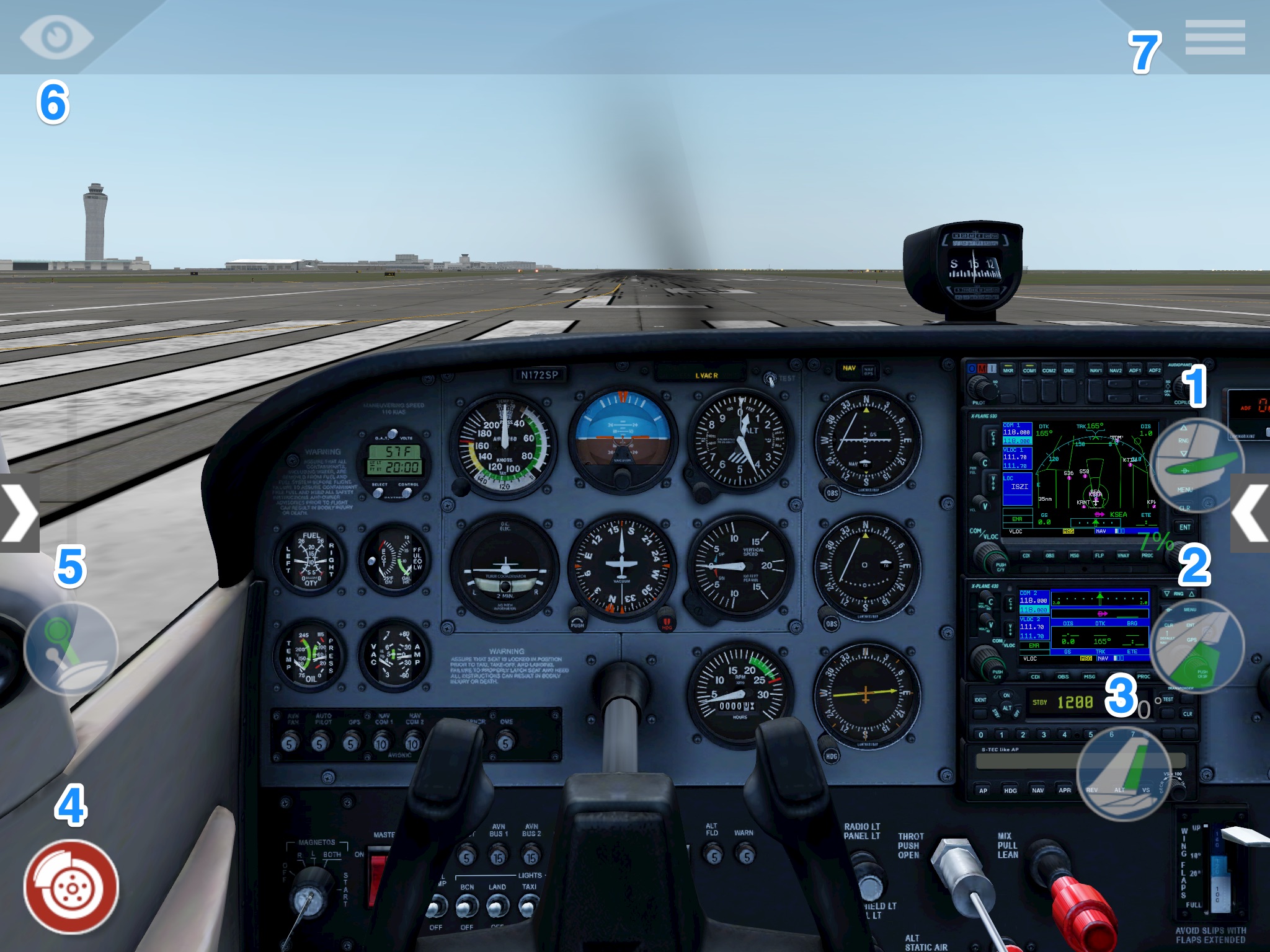
X Plane Mobile Manual
This article will cover the six main pieces of equipment, often referred to as the "six packs," of any airliner.
While the app itself is relatively easy to read, the mechanics behind its operation are a bit complicated. Also, some tools have many names and abbreviations, which can be unnecessarily confusing.
To understand why these six main tools look the way they do, it's important to understand how they work.

The six main instruments ("six packs") are the airspeed indicator (AI), head indicator (HI), speedometer, airspeed indicator, altimeter, and velocity indicator (VSI).
Horizontal Situation Indicator
Gyroscopes use gyroscopes to create air (vacuum) or conduct heat. A gyroscope consists of a rotating disk that moves around an axis, depending on the application.
In a motorized gyroscope, such as a gyroscope, an electric motor spins a dial. In the heating system, an air pump driven by the engine reduces the pressure in the components. The filtered air is placed on the disc inside the bag at high speed, causing it to change at high speed.
The cause of the spatial stability (also called gyroscope inertia) is the spinning disk inside the gyroscope. As long as there is no external force acting on the spinning disc, it will remain in its original shape. The stability of a rotating disc increases with increasing disc size or speed. The disc inside the aircraft gyroscope is made of a heavy material that spins the disc at high speed. The gyroscopes in these devices spin at approximately 10,000 revolutions per minute (RPM).
Since the rotating disk maintains a constant position in space, it can be used to determine the flight characteristics associated with the rotating disk. While the gimbal (the frame around the rotating disk) moves freely, the aircraft moves smoothly around the rotating disk.
Pilot Mall Launches Configurable Training Device
When a force is applied to a gyroscope (i.e. a rotating disk), the force does not act at the location where the force is applied, but "causes" the disk to rotate 90 degrees and - to do it around there. In other words, if the Apply force to the disk and it will "spin" or "turn."
Acceleration is primarily caused by friction in the gyroscope and forces experienced during motion, such as acceleration or deceleration.
Due to this method, the gyroscope will "drift", resulting in inaccurate readings. Therefore, pilots must periodically check the gyro equipment and adjust its indicators appropriately.

Artificial Intelligence (AI), sometimes called Artificial Horizon (AH), is a behavioral tool in aviation.
The Six Pack: Basic Flight Instruments
Artificial intelligence provides pilots with information about the plane's bank angle and weather space. This allows the pilot to define the behavior of the aircraft and modify it.
AI creates the basis for tool analytics because AI is a good indicator of what others are going to show. For example, if the AI is showing a bank angle other than wing height, the title will most likely indicate a turn in the direction of the bank.
AI works best during instrument flight rules (IFR) flying, where the weather outside may not.
The AI displays specific signals that allow the pilot to determine the altitude and part of the flight slope that was successfully entered.
Aircraft Pressure Measuring Instruments
The aggressive attitude profile is limited to 100 degrees bank angle and 60 degrees pitch angle. If these limits are exceeded, the attitude indicator will descend to "Descent" until the aircraft has brought its level and bank angles back within the limits and the AI will receive the correct position. It may take a few seconds to a few minutes for the AI built-in gyroscope to stabilize and the APP to display normally.
The Head Indicator (HI), also known as the Direction Indicator (DI) or Direction Gyroscope (DG), is the primary direction indicator in an aircraft.
The HI has rotational error and needs to be periodically corrected to the correct heading using a magnetic compass.

Some head indicators have a head error feature that allows the pilot to move any head and color markers on the HI for reference.
Pp Flight Instrument
The Primary Display should not be confused with the Horizontal Position Indicator (HSI), which is a variant of the Primary Display that includes VHF Omnidirectional Range (VOR) and Instrument Landing System (ILS).
A turn monitor, also known as a turn and bank indicator, is a growing class of turn and stop indicators that provide information about bank angle and aircraft configuration.
An aircraft is in controlled flight when rudder inputs prevent the aircraft from pitching or turning flight (like a car), or when its landing gear is aligned with runway height during level flight.
This information is displayed by a "ball" within the application itself. ball inside
Garmin Updates Gi 275 Electronic Flight Instrument, Adds Gfc 500 Autopilot Compatibility & More
Experimental aircraft instruments, quality aircraft instruments, basic aircraft instruments pdf, aircraft navigation instruments, pressure instruments in aircraft, 6 basic instruments in aircraft, six basic aircraft instruments, aircraft gyroscopic instruments, 6 basic aircraft instruments, basic instruments, basic aircraft, aircraft instruments
0 Comments